
Compressive Seismic by Acquisition Type
Fig. 1 - Seismic source lines in Alberta. Pembina Institute photo by David Dodge.
Sources
Sources tend to have some freedom as to where they can be placed. For operational reasons, they are usually limited to a fixed path. Source lines in land acquisition are limited by access and line-clearing costs. However, shot point locations can vary within a source line. Sail lines in marine acquisition are imposed to maximize efficiency. The spacing of these sail lines, though, can be varied.
Fig. 2 - iDrop self-guided ocean bottom node.
Receivers
Receivers fall into two broad categories: wired and wireless. Wired receivers, such as geophone strings, towed streamers, and ocean bottom cables, have fixed placement and cannot be arbitrarily moved. Wireless receivers are generally referred to as nodes (land, ocean bottom, etc.). They are fitted with a battery and usually record data on each node independently. As such, they can be placed arbitrarily within the limits of the terrain. (See related: iDrop)
Compressive seismic survey conversion
There are many possible scenarios for converting a regular acquisition layout to a CS-optimized design. In the interest of brevity, we will focus on two typical scenarios based on our patented regular indexed design.
Scenario 1 – Land orthogonal geometry
A typical land acquisition setup is with perpendicular source and receiver lines. The line placement constraint is imposed to minimize line clearing costs. A CS conversion of this geometry, following In-Depth's standard land CS workflow, would look like Figure 3. It preserves the source and receiver line pattern and implements the CS design by dropping both source and receiver stations along their respective lines. The advantage of this CS1D design is the reduced source and receiver effort while not adding to the line-clearing cost.
Fig. 3 - Land orthogonal survey before and after CS conversion.
Scenario 2 – Marine OBN geometry
A typical ocean bottom node survey places a source vessel and nodes on the sea floor. Sail lines in Figure 4 below are shown in red. On the source side, since the vessel must sail along the line, there is no advantage to skipping shot locations unless there is some operational constraint that needs to be overcome, such as compressor recharge time being longer than the desired spacing between shots. The CS conversion of the source effort usually results in a varied sail line spacing with no change to the shot spacing. On the node side, since there is no line-clearing constraint, there is no need to preserve receiver lines. The CS2D conversion can drop nodes in both x and y directions to achieve the optimal design. The reconstruction accuracy increases dramatically by allowing this 2D variation in node position. There is also the ability to do flexible designs. In the example below, after CS conversion, the survey center has a higher node density than the surrounding area.
Fig. 4 - Marine OBN survey before and after CS conversion.
CS1D vs CS2D
Scenario 1 is an example of CS1D, which is appropriate when there is a need to preserve source and/or receiver line geometry while still reaping the benefits of CS. Scenario 2 is an example of CS2D, which is only possible when sources and/or receivers can be moved freely on the surface.
We have studied the differences between CS1D and CS2D using SEAM benchmark data. From our results, CS2D can achieve the same signal-to-noise ratio as CS1D with about 20% fewer samples. For example, to achieve a signal-to-noise ratio of 20dB down, CS1D needs about 50% of the samples retained, while CS2D only needs about 30% of the original samples. This is a massive potential decrease in acquisition effort, so if the acquisition method supports it, we always recommend using CS2D over CS1D.
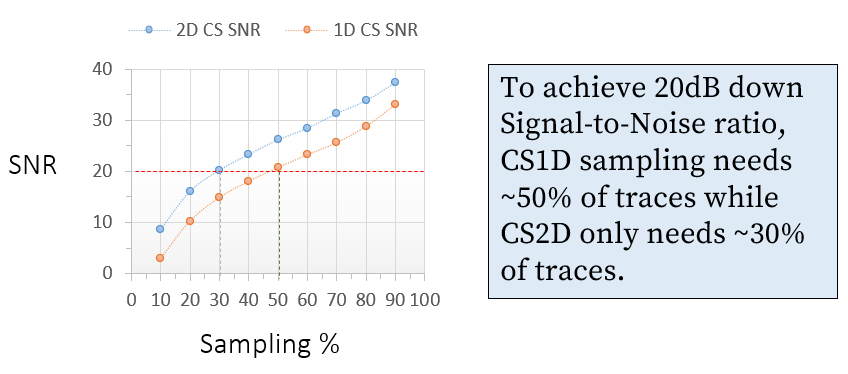
Fig. 5 - Signal to Noise Ratio (SNR) as a function of sampling percentage for both 1D and 2D CS Designs. 2D CS consistently shows higher SNR, requiring significantly fewer traces to achieve the same reconstructed data quality.
Conclusion
Compressive Seismic’s value proposition is that it allows for reduced acquisition cost while obtaining the same data quality after reconstruction. Seismic acquisition is expensive and managing risk boils down to having the appropriate, optimized design that reduces the overall project cost while producing a quality product at the end. In-Depth’s patented methods and years of experience in the field make us the go-to choice for modern CS-friendly surveys.
